The basics of limit switches 2 table of contents the wiring in a non plug-in switch is brought in through the conduit entrance at the bottom of the body/receptacle the wiring terminals are accessible through the front of the switch by removing a cover plate the cover plate is attached by two. Circuit diagram for limit switch. What is the purpose of the switch shown in this schematic diagram? this device is known as a switch, and its purpose in this circuit is to establish or interrupt the electrical continuity of the circuit in order to control the light bulb beginning students often find the terminology for switches confusing, because the words open and closed.
circuit diagram for limit switch
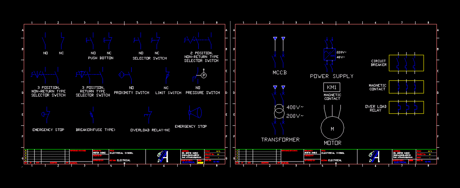
The diagram symbols in table 1 are used by square d and, where applicable, conform to nema (national electrical manufacturers a ssociation) standards disconnect circuit interrupter circuit breakers w/ thermal ol circuit breakers w/ magnetic ol limit switches foot switches pressure & vacuum switches liquid level switches temperature actuated. This switch can be wired up as a reversing switch for a motor. some dpdt switches have a central off position. contact switch symbols the following switch symbols present to make contact switch, break contact switch, two-way contact switch, passing make contact switch, spring return switch, stay put switch, limit switch, and circuit breaker.. Most electronic circuits contain an on/off switch. in addition to the on/off switch, many circuits contain switches that control how the circuit works or activate different features of the circuit. one way to classify switches is by the connections they make. if you were under the impression that switches simply turn circuits on and off, […].
get link reference
