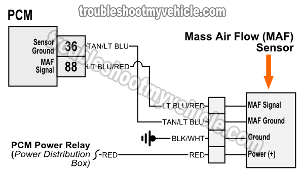
Mass air flow sensor wiring diagram – bosch mass air flow sensor wiring diagram, delphi mass air flow sensor wiring diagram, gm mass air flow sensor wiring diagram, every electric structure is made up of various unique pieces each part should be placed and linked to other parts in particular manner if not, the arrangement won’t function as it ought to be. Gm maf wiring diagram. Testing a 3 wire gm mass air flow sensor - before replacing it based on the p0102, test to confirm the wiring integrity is good (the power and ground, as well as the computer and signal wire).
gm maf wiring diagram
The frequency specification i quote in this video will differ depending on engine size but the electrical tests shown, particularly in part 2 are universal and apply to all gm maf sensors the.
get link reference
